Invisible Connections: Total Solution for Precast Concrete Connection
With the increase in reliance on precast concrete, Halfen Moment Group is ideally positioned to facilitate this transition due to its access to state-of-the-art connection technologies from its sister companies and partners in Asia, America and Europe.
One such technology is – Invisible Connections. It is a modern way of connecting precast concrete without use of corbels or angles.
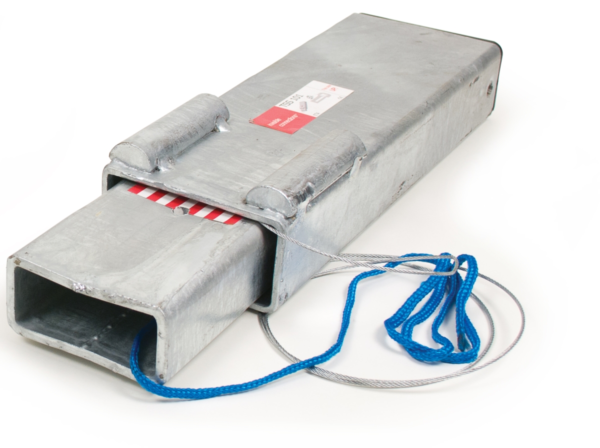
TSS101
What is Traditional Technology?
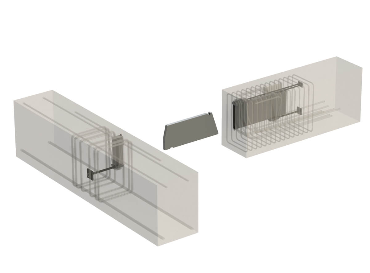
TSS telescopic connectors by Invisible Connections were developed specifically to address these problems. They are a proven technology developed in Norway and used extensively throughout Europe due to the independently tested and certified European Technical Approval (ETA) that provides engineers with peace of mind about their capacities.
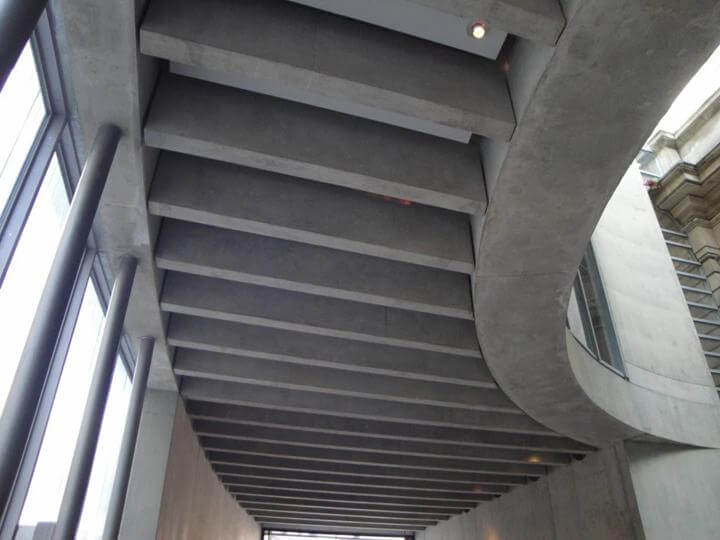
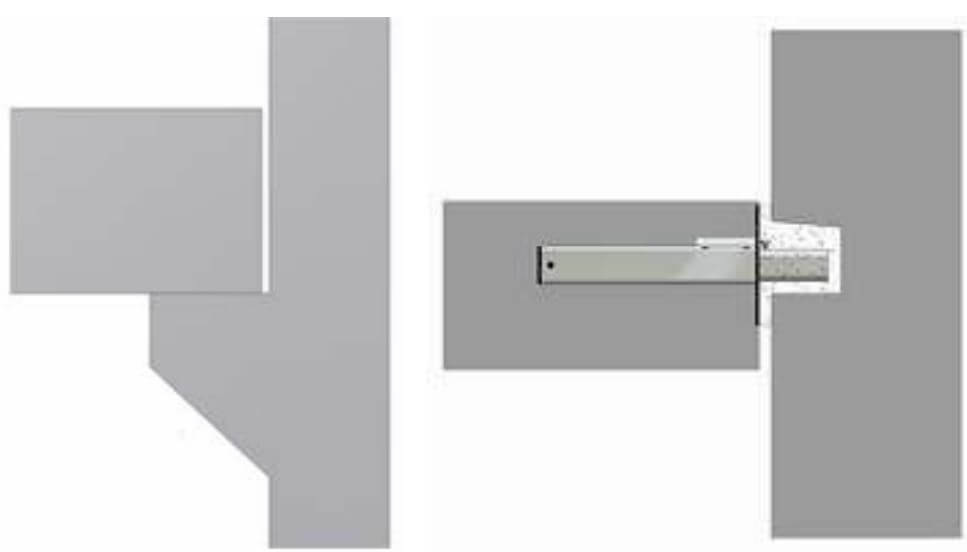
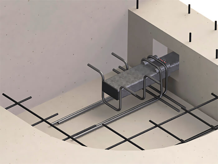
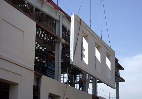
The TSS units are used for a concrete component with an exposed concrete finish such as a stair landing. When erecting the elements on site, the inner tube is pulled out with a wire to fit a recess in the wall with a safety device to ensure the inner tube is correctly located in the recess.
Conventional construction with corbel VS Corbel free construction using Invisible Connections
Why Invisible Connections?
Types of Invisible Connections
TSS & RVK
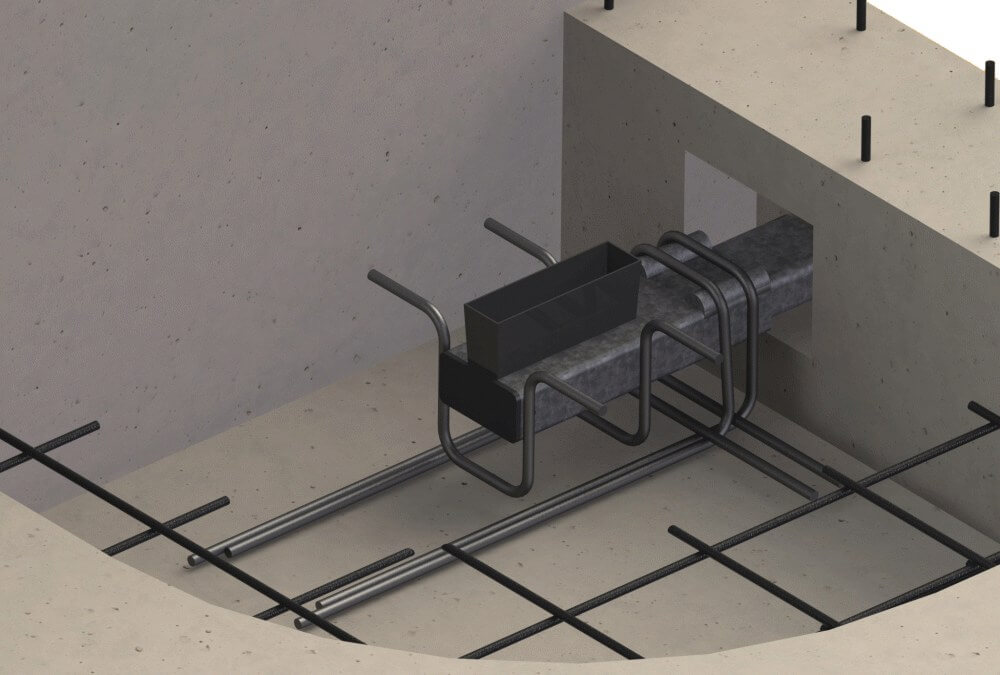
2) BSF For Precast Beam to Column Connections.
BSF
3) DTF/DTS For Precast Double T connections.
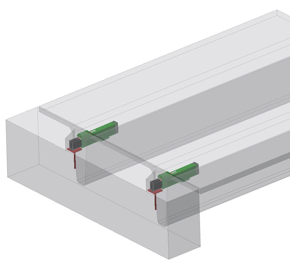
DTS
Advantages of Invisible Connections
After installation, there is an invisible connection, with no visible supports.
2) Reduce impact sound from the stairways
The Invisible Connection System has several ways for sound insulation. From the more ordinary to the remarkable sound reduction.
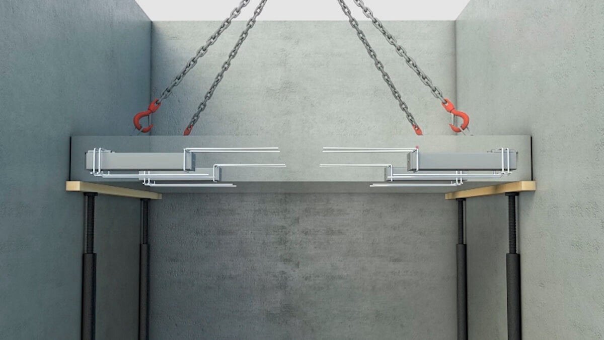
3) Safe and simple installation on site
With a crane the elements are safe and quickly located in the shafts. The correct method is to support the elements from beneath, level the element and pull out the inner tubes into the recesses. For the permanent connection, the recesses are then filled with mortar.
4) No welding or bolting on site
By using our systems you avoid welding and bolting on site. Only filling up the recesses with mortar is needed. Uniform performance.
5) Simple design of walls
Easy to plan the recesses in both precast walls and in moulds on site, due to standard location and sizes. Less use of crane time on site. The installation time is shorter, compared to similar systems. Saving crane hours and money.
6) Standard box for wall recesses
The Invisible Connection System has also standard boxes for planning the recesses. These are corresponding to the size of the units. For steel moulds, they are magnetic.
7) Technical approved systems
The Invisible Connection System is ETA approved system.
No visible corbels and reducing the waiting time for the crane
For further details, please contact our Malaysia HQ office or visit our office where we can showcase you the actual Invisible Connections products!
Related Articles You May Be Interested
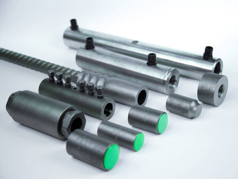
Rebar Coupler for Structural Integrity
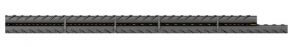
Traditional Method of Connecting Rebars
For more than a century, construction practices in the building of concrete structures have focused on the use of steel reinforcement to transfer tension forces. Lap splicing became the traditional method of connecting the steel reinforcing bars, largely due to a misunderstanding that lap splicing is a “no-cost” splicing. Lap splicing requires the overlapping of two parallel bars. The overlap load transfer mechanism relies on the concrete around it to transfer the load.

However, lap splicing is not always the proper means of connecting reinforcing bars for the following reasons:
• Use of lapped joints is time consuming in terms of design and installation
• Lead to serious congestion within the concrete due to the increased lapped rebar volume
• Lapped joints are very dependent upon the quality of the concrete for load transfer
• Poor compaction of the concrete will compromise the performance of the joint and might result in ‘honeycombs’
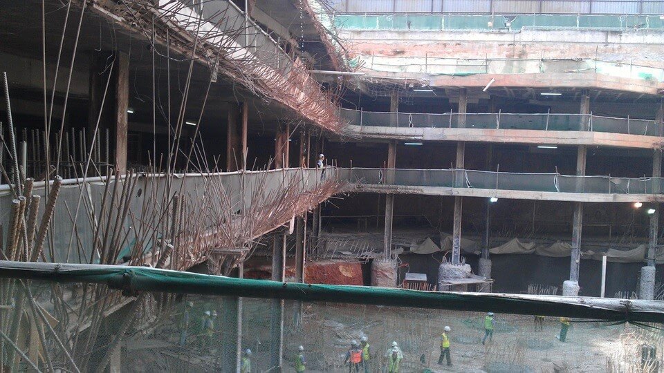
Stains, corrosion and breakage of starter bars left for future extension
Reinforcement Coupler System: The Technology for Present and Future
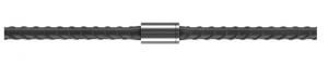
Today, the use of mechanical splices or widely known as rebar coupler is superior in its load transfer to lapped splicing as it creates a direct mechanical connection between the 2 bars which is similar in its behavior to a continuous reinforcing bar.

In general the use of coupler for rebar will:
• Improve structural integrity
• Improve design options
• Achieve an ideal balance of steel and concrete by eliminating unnecessary rebar
• Reduce the congestion and weight of the structure.
• Lessens the amount of embodied CO2
• Reduce the rebar cost as lapping uses more steel than couplers
So there are only advantages…

Rebar coupler avoids bend and rebend of reinforcement bar and improve site safety
Other than the benefits listed, trends toward stronger buildings, increased geography impacted by seismic zone mapping and increasing needs for safer buildings will also affect the potential value of a building. Hence, with many different types of reinforcing coupler system available in the market, designers can easily incorporate them into future plans.
A wide range of rebar couplers for different applications is available at Leviat, rebar coupler supplier. As the strength of the coupler connection depends on qualitative threading of the rebars, do only rely on a serious partner who offers consistent and controlled quality threads.
Explore the range of MOMENT® couplers available here.
Related Articles You May Be Interested
Precast Lifting Design

Precast Lifting Design
Often it is more important to have relevant experience in precast design, coupled with some good reliable design tools rather than a degree in structural or civil engineering.
As it is heavily related to the crane and rigging industries, lifting design is one of the few remaining structural designs that still operates predominantly on a working stress design model rather than limit state design. This is done largely to ensure that the risk of overloading of the lifting anchors is kept to a minimum.
Therefore, Safe Working Load of anchor > applied service load.
Also, care needs to be given to assess each load case including demoulding, storage, transportation and erection as the carnage and concrete strength could differ for each.
Flat panels can be relatively straight forward, but volumetric constructions add another dimension that can result in additional issues to overcome.[/vc_column_text][/vc_column][/vc_row]
Determination of Applied Service Load
Element weight, based on 2400-2500kg/m3 is the initial start point for any lifting design. However, there are a number of additional factors that need to be taken in to account:
1. Suction between the concrete element and the formwork can vary depending on the material and geometry of the casting bed. For example:
")
These values are for flat casting beds only and additional factors need to be applied if the geometry is different.
2. Sling angle factor for the rigging also affects the amplitude of the service load on the anchor and is often directly affected by the amount of height clearance at the precast factory.
It is generally accepted that a sling angle (α) of 60 degrees (β=30) is the best compromise and therefore tends to be the default for most lifting designs.
")
")
Dynamic Impact Factor
Another important consideration is estimating the effect of dynamic impact on the lifting system.
This is based on engineering judgement about the type of crane and ground conditions. A fixed gantry crane will have much less dynamic impact than a crawler crane moving over uneven ground.

* If other values from reliable tests or through proven experience are available for Ψdyn then these may be used for calculation.
Determination of Safe Working Load
Each anchor is allocated a load class, but this can give a misleading level of confidence as it is only the steel capacity and the concrete capacity can be much lower.
Steel Capacity
The steel capacity is stamped on every anchor head as is determined by taking the characteristic (5% fractile) strength of the anchor and dividing it by 3. Therefore, a 5T anchor will typically survive a load of 15T before it breaks.
Concrete Capacity
There are a few different concrete failure mechanisms that can occur and for a detailed analysis you should refer to VDI BV-BS 6205 or CEN/TS 1992-4. However, concrete cone failure is the most well-known and is a function of the concrete strength at time of lift, the edge distance and the embedment depth of the anchor. The general safety factor given to concrete failure mechanisms is 2.5 against the characteristic (5% fractile) strength of the concrete. It is lower than the steel as it is generally unaffected by multiple uses.
For a detailed analysis of your anchor capacity, please consult the Halfen Moment’s engineering team.

Related Articles You May Be Interested