
10 Tips To Stay Safe At Site In 2019
Safety is our core value in Halfen Moment and it is the responsibility of all of us to work towards our goal: ZER0 fatalities and ZERO accidents. There are plenty of guidelines and regulations that we should follow on construction sites or workplace, and almost all of them pertain to the safety of the people who work there. Here are 10 common construction site safety tips:
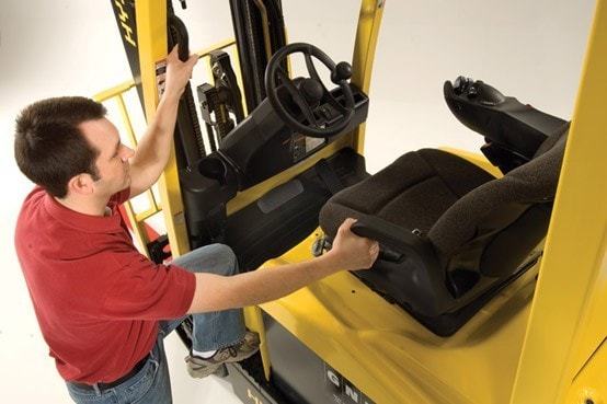
Use Caution When Climbing On and Off Equipment
Falls when climbing on and off equipment is common, as is someone getting injured because they got stuck in the process. No one should stretch more than they should to grab onto the handles, nor should anyone carry anything as they are getting up or down. It is also important to never jump down from a machine, as they are when the most accidents happen.
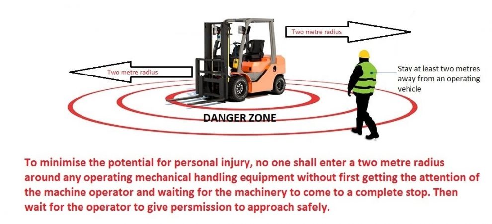
Stay Away from Operating Machinery
It is common for workers who are waiting for the next step of their job to simply congregate in one area and patiently watch as someone else is doing their job. This is normally not an issue except when those people are standing too close to operating machinery. Most of the time nothing will happen, but accidents usually do not announce themselves first, so workers should stay away out of extreme caution.
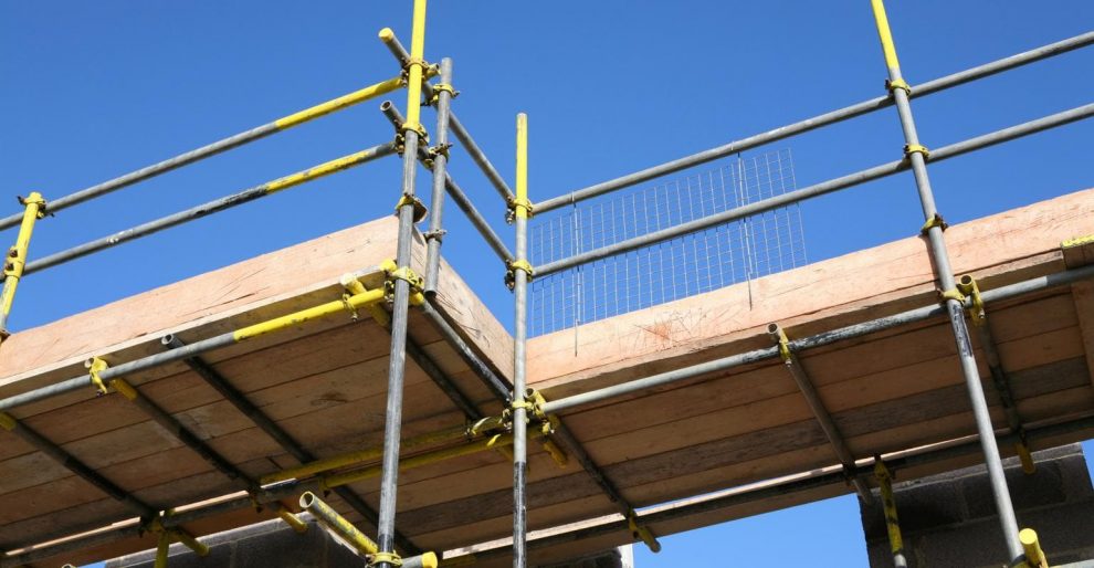
Use Caution Around Fall Hazards
Every construction site has fall hazards and it is the worker’s job to be aware of what they all are. Safety systems should be in place in those areas to prevent falls from occurring for example, guardrails, safety nets, safety cords, and personal fall arrest systems.
Use the Proper Ladder Height
Some construction workers will try to get away with using a shorter ladder than they should, simply because a taller one is not available. This should be avoided if possible, because every time a construction worker stretches past the point that they should on the ladder they are using, they take the chance that they will fall off the ladder or the ladder will tip over and take them with it.

Keep an Updated First Aid Kit
That first aid kit from five years ago is going to contain medication that is outdated and band aids that are most likely past their sticky stage. Everyone should be prepared with an updated first aid kit. This kit should include disinfectant, ointment, painkillers, and bandages and gauze of all sizes.

Never Use Damaged Equipment
When there is work that needs to be done, some construction workers will simply use what they have available even if that item is damaged. That is never a good idea, as that damaged piece of equipment can cause an injury rather quickly. Some damaged parts can include a worn-out cable, worn-out cords, and a worn-out harness.

Never Unplug a Tool by the Cord
At the end of a long day or after a long tedious project, many construction workers may be tempted to unplug the cord of the tool they are using by simply giving it a good yank. This motion can damage the tool over time and it can also cause injury to a person. It is better to take the two extra seconds to go over and pull the plug out of the outlet, because those two seconds can mean the difference between life and death on occasion.

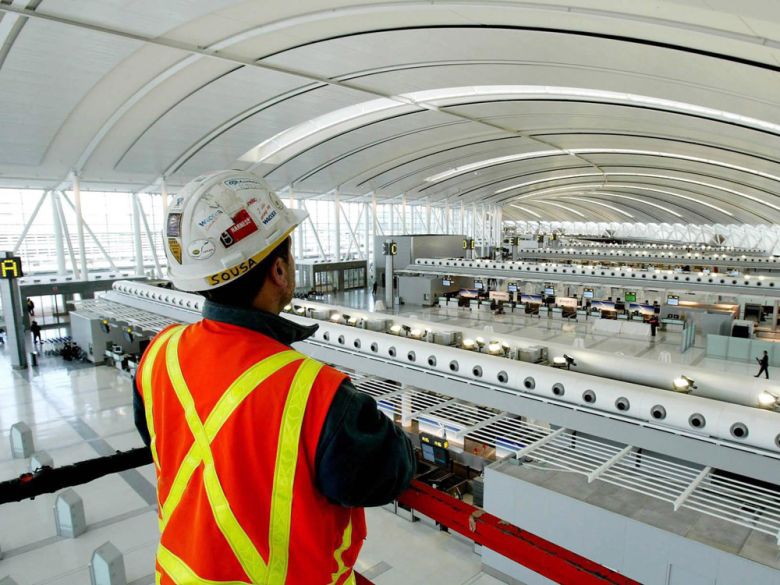
Be Aware of Surroundings at All Times
Construction job sites are busy places, which is why workers will want to be aware of their surroundings at all times. No one thinks that something bad is going to happen to them as they are simply sitting there taking a break, but one second of unawareness can lead to a person getting hit on the head by a falling object or getting run over by a piece of machinery.
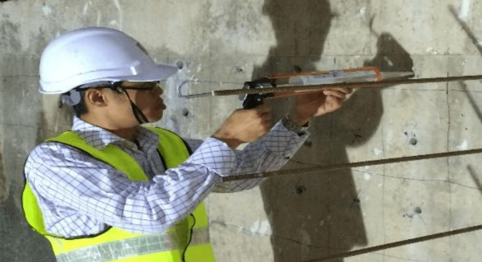
Use Personal Protective Equipment (PPE)
Employers have duties concerning the provision and use of personal protective equipment (PPE) at work. PPE is equipment that will protect the user against health or safety risks at work. It can include items such as safety helmets, gloves, eye protection, high-visibility clothing, safety footwear and safety harnesses. It also includes respiratory protective equipment.

Manual Handling Tips for Safe Lifting
Over 40% of site injuries come from handling goods. Costs from handling errors leading to injury may include compensation and lost productivity. Putting in place control measures to help employees understand how to lift, push and pull correctly can solve the majority of these accidents.

These safety tips are designed to keep everyone safe on the construction site, and while many of them are basic common-sense things, they are still overlooked numerous times a day around the world. The one thing that every construction worker needs to remember is that accidents happen and everything that they do when they are on the job can be potentially hazardous in one way or another. Therefore, they need to be cautious every minute of the day, so that they can leave and go home the way that they came.
The Guide to Select the Right Concrete & Plastic Spacer
Selection of the Right Spacer
Concrete or Plastic spacers are little accessories used to maintain the position of rebars in the concrete structures before pouring the concrete. This is necessary to maintain a clear distance (cover) between the surface of the concrete and the rebar, as if there is insufficient cover, the rebar will start to corrode and result in spalling concrete. These spacers then become the permanent part of the structure after pouring. Although different types of spacers have similar features but the selecting the right one will ease the construction efficiently and safely. Hence, the selection of spacer will be based on the following factors:
Height of Spacer
The minimal height of spacer is equivalent to the dimension of the spacer to form the exact concrete cover for the rebar in concrete. Hence, this is the key specification needed while ordering. With the multi-dimension spacer, the heights for supporting the rebars will vary in depend on the position of installation. In a project, where the reinforced concrete structures have various concrete cover thicknesses, it is practical to select the multi dimension spacers with the appropriate dimensions.
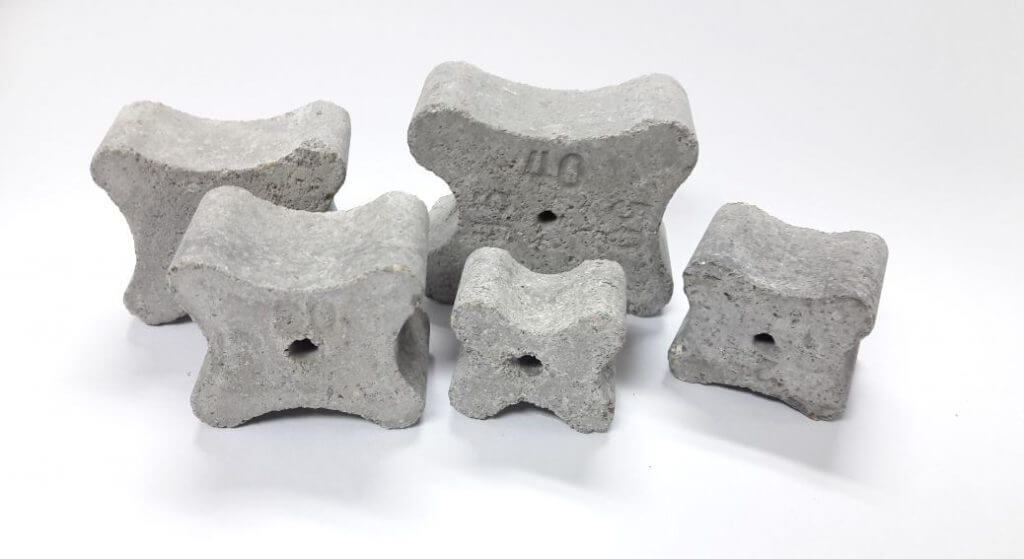
Different heights of concrete spacer
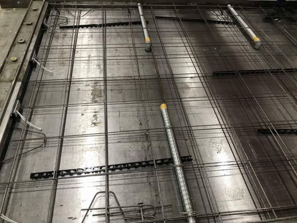
Firmness of Subgrade
The spacers placed under the rebar mesh will be impacted by the forces from above such as the weight of rebars, workers and machines. If the contact area of the spacers with the soil/stone subgrade are not suitable, they can settle during construction. This condition will reduce the concrete cover thickness as required. Hence, if the subgrade is not firm, the spacers will need sufficient contact areas or some additional plates to spread the load from the spacer.

Suitable and sufficient of concrete spacers are essential to avoid reduction of concrete cover thickness
Material
The material of the spacer being selected needs careful consideration as each material type has its pros and cons. Plastic spacers provide no compromise in terms of serviceability, but are generally weaker than steel and concrete versions. Therefore, if the cage being supported is very heavy or if the rebar has a high risk of being walked on, then plastic spacers should only be selected with extreme care. Steel spacers are more robust, but come with the added problem that there will be some non-structural steel within the cover zone. This can often lead to small rust spots being visible on the concrete surface, so if the surface is exposed and visible, steel spacers should also be avoided. In general, the simple concrete spacers can be used for all structures, providing the concrete spacer grade is similar to that of the surrounding concrete. Too much variation in properties can lead to localised cracking and compromise the integrity of the concrete locally around the spacer. There are many kind of spacers with various shape and use for selection. The users should firstly analyse the conditions and then select the right product in order to obtain the best efficiency.
Moment plastic fast spacer- Designed for low loads
Connection of Spacer and Rebar
There are a few examples of common options of connection between spacer and rebar:
a) Spacers are placed on horizontal surface and support the steel rebar above. By the weight and fixation of steel mesh then the spacers can be fixed without the binding connection. In this case, the spacer works as the blocks to form the right cover thickness. The long plastic spacer (continuous spacer) is the most cost effective alternative, placing under low loads area. It can be used in non-critical locations.
b) The spacer with tie wire or plastic/steel hooks for connection with rebar. By hook or tied-wire, the spacers are fixed at right positions and not falling out. This kind of secure connection is critical when spacers are vertically placed (when rebar cage is lifted or vibration of concrete).
c) The spacer with holes at their centers for inserting the rebar. Consequently the spacer can connect with the rebar and will not be taken apart even if the rebar moved.
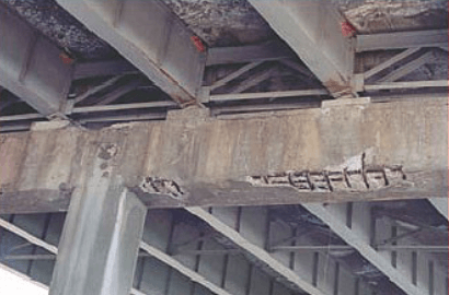
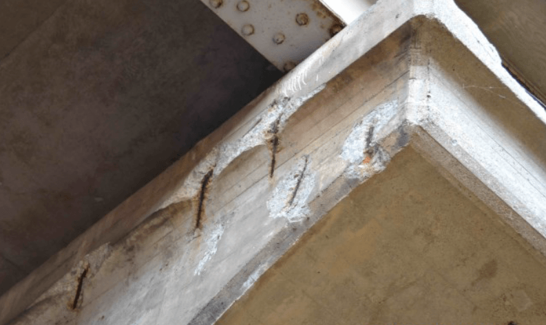
Consequences of without proper concrete spacer- Vulnerable to corrosion and the concrete to early deterioration
Related Articles You May Be Interested In

3 Easy Ways of Preparing Starter Bar without Damaging the Formwork
Starter bars are rebars cast into the concrete to give a lapped connection to provide continuity of reinforcement across a cold joint or construction joint. Planted horizontally to the existing concrete element in which they are installed, they are also used to extend or rehabilitate existing bridges, roads and building structures.
The easiest and most inexpensive way of designing starter bars is to have them projecting from the concrete surface. However, complications arise when starter bars need to project through the formwork. Timber formwork needs to have pre-drilled holes in the accurate positions which may render the formwork unusable for future projects and cause difficulties when stripping. Not mentioning if it is steel formwork, which creates even greater problems.
Besides, projecting rebars can cause a safety hazard for both trips and falls. The cast in starter bars should have protective caps to minimize these risks. Projecting bars in precast concrete cause additional problems with storage and transport, and as a result are not commonly used. Rebar will also tend to rust easily when exposed to weather.
Here are 3 easy ways of preparing starter bar without damaging the formwork:
Organic Resin
Other than having starter bars with cast-in-situ in method, starter bars may be embedded in organic or minerallic mortars from a previously cast surface. Holes are drilled in the concrete at required positions and the bars are fixed with mortar. There are many suitable mortars available, although the higher bond strengths come from organic system, so these tend to be the most popular. The organic resin may be introduced via a gun/dispenser, or in a glass capsule that is broken by the bar, allowing mixing to occur. Care must be taken to treat the drilled hole as recommended to ensure adequate anchorage. The resin method is particularly useful for fixing of items such as posts or barriers where accurate position is needed.

Injecting organic resin while withdrawing the nozzle as the hole fills. Insert rebar with a slight twisting motion.
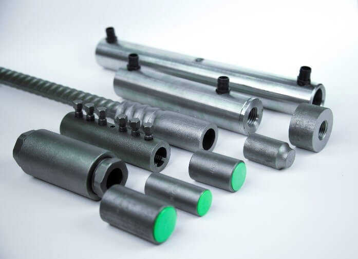
Mechanical Splice System
The easiest way to avoid having to have bars projecting through the formwork is to use a mechanical splice system (Rebar coupler). Simply engage a coupler onto the threaded rebar, which is then cast flush with the concrete (a coupler capping can prevent the concrete slurry from flowing into the coupler). The second bar is then connected to the coupler. To avoid loss of cross section, the end of the bar is ‘enlarged’ by cold forging the end of the bar before threading. No drilling is required in the formwork.

Starter bar from diaphragm wall using Moment Jointec Coupler
Reinforcement Continuity
An alternative system (to ensure cost effectiveness for smaller bar diameters) has pre-bent and pre-spaced steel reinforcement supplied in a pre-galvanized steel box that is dimpled and flanged for maximum concrete bond. The system is used to enable efficient and reliable reinforcement continuity for sections of concrete structures that are poured in subsequent phases without the need to drill formwork.
This system not only improves on site productivity due to its installation speed, but also provides significantly higher shear capacities compared to traditional methods due to a higher shear friction. This enables us to reduce the amount of steel bars required to carry the same vertical load; reducing costs and embodied CO2 in the construction.
Installation is simply achieved by nailing the casing to the formwork or wiring it to the existing reinforcement bar cage prior to concreting. After removal of the formwork the lids of the box is removed and the bended bar being straightened and ready for connecting.

Moment Box is the only rebar box capable of making an anchoring which can transfer significant force around the structural joints.
Fill In The Contact Form & Let Us Drop You A Call For A Free Consultation!
Related Articles You May Be Interested

Industrialized Building System: The Malaysian Approach
What is the Industrialized Building System(IBS)?
An Industrialized Building System (IBS) refers to a technique of construction whereby components are manufactured in a controlled environment – either onsite or offsite – placed and assembled into construction works. The term IBS is often tossed around in the world of construction in Malaysia, overseas it goes by other terms such as Pre-fabricated construction, Modern Method of Construction (MMC) or even Off-site Construction.
IBS is also defined as an integrated manufacturing and construction process, carefully planned organization, and efficient management, preparation and control of resources, activities and results from the highly developed components. The manufacturing of the components are done with machines, templates, and other forms of machinery and equipment. Components manufactured off-site, once completed, will be delivered to the General Assembly and erection of the construction site.
The five main IBS groups present in Malaysia:
• Precast Concrete Framing, Panel and Box Systems – pre-cast columns, beams, slabs, 3-D components (balconies, staircases, toilets)
• Formwork Systems – tunnel forms, EPS-based forms, beams and columns moulding forms, permanent steel formwork

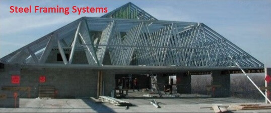
• Steel Framing Systems – steel beams and columns, portal frames, roof trusses
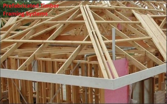
• Prefabricated Timber Framing Systems – timber frames, roof trusses
• Block Work Systems – interlocking concrete masonry units (CMU), lightweight concrete blocks

The Benefits of the IBS
• Higher quality products and minimum waste, due to a factory work environment that is easier to control.
• Elimination of conventional timber props and an obvious decrease of supporting materials, through the use of complete assembly elements or prop system for the onsite casting process.
• Stronger and safer work platform, produced through a complete assembly element.
• Faster completion, due to the introduction of prefabricated components to replace onsite fabrication.
• Safer, cleaner and more organized site, due to the reduction of construction waste, site workers and prefabricated construction materials.
• Cheaper total construction cost, resulting from the above factors.
The general idea the IBS is to realign effort and resources away from the less controlled environment of the construction site to the more controlled environment of the workshop. The implementation of IBS aims to create higher quality levels of construction at its core through control and consistency. As it stands right now, the implementation of IBS in Malaysia is met with many challenges but IBS is the future of construction and will play a key role in the future of the industry.
Overview of our solutions for the Precast & IBS Industry
The building below shows some of the possible applications for Leviat products in the precast/IBS industry, from mechanical splices to specifically designed precast technologies for lifting and connections. Whether for civil engineering or in residential and commercial projects, Leviat products play a crucial role behind the concrete.
Click here to learn more about our construction accessories for the IBS Precast Industry

Related Articles You May Be Interested In
Mechanical Splices vs Lap Splicing
Lapping of rebars has long been considered an effective, economical splicing method, but today’s more demanding concrete designs are forcing builders to consider alternatives.
In almost all reinforced-concrete structures, rebars must be spliced. The required length of a bar may be longer than the stock length of steel, or the bar may be too long to be delivered conveniently. In either case, rebar installers end up with two or more pieces of steel that must be spliced together.
Lap splicing, which requires the overlapping of two parallel bars, has long been accepted as an effective, economical splicing method. However, there has been a shift in recent years. Continuing research, more demanding designs in concrete, new materials and the development of composite materials have forced designers to consider alternatives to lap splicing, which is mechanical splices.
Mechanical splices are mechanical connections between two pieces of rebar that enable the bars to behave in a manner similar to continuous lengths of rebar. Mechanical splices join rebar end-to-end, providing many of the advantages of a continuous piece of rebar. They are more reliable than lap splices because they do not depend on concrete for load transfer. Today, a range of mechanical splices are available to ensure that a precise, reliable connection can be made quicker and easier.
The 5 Key Benefits of Mechanical Splices
Mechanical splices offer builders the following benefits:
1) Improved structural integrity
Mechanical splices maintain load path continuity of the reinforcement, independent of the condition or existence of the concrete. To use splices in tensile regions, they must be able to develop the full strength of the rebar and not create a weak point. Therefore the performance of the system is assured throughout the strain-hardening region where plastic deformations occur. In seismic applications, mechanical splices maintain structural integrity when bars are stressed beyond yield, allowing the predictable formation of plastic hinges.
2) No reliance on concrete for load transfer
In coastal regions, rebar corrosion can produce concrete delamination and spalling. Since lap splices transfer load through the surrounding concrete, when the concrete is gone, the lap splice in effect has failed. Mechanical splices do not rely on the concrete for load transfer and therefore maintain the structural integrity.
3) Elimination of lap splice calculations
Mechanical splicing does away with the tedious calculations needed to determine proper lap lengths and the potential calculation errors.
4) Reduced material costs
Because mechanical splices do not overlap, less rebar is used, reducing some of the material costs. This cost savings can be particularly significant for jobs requiring expensive epoxy- coated or galvanized bars, since building codes require up to 50% longer splice laps for these bars than for standard rebars.
5) Reduced rebar congestion
A common complaint of concrete placing crews is that they can’t get the concrete through the rebar cages. Laps effectively double the steel to concrete ratio, and the resulting congestion can restrict the flow and distribution of larger aggregate particles and limit the effectiveness of vibration. Mechanical splices will significantly reduce this congestion.
Cost Comparison
Although the advantages of mechanical splices are well recognized, a major concern has been their high cost for applications where the codes permit the use of lap splices. But is the perception that mechanical splices cost more than lap splices a reality? By using couplers, contractors can be more cost efficient, able to achieve from 20-50% of cost savings compared to lap splicing. Apart from that, there are many other savings which can be anticipated such as;
Reduction no. of joints
6 meters length will be most ideal for joining and this would result in reduction of no. of laps by,
Assuming height of building: 100 metres
Typical floor height: 3.2 metres
No. of laps: 100 / 3.2 = 31 laps
No. of coupler joints: 100 / 6 = 16 joints
Therefore reduction in no. of laps: [(31-16)/31] x 100% = 48%
Minimal wastages of HTDBs
Assuming floor height of 3.2m and lap length of 1.275m
Length of steel bar per floor is : 3.2m + 1.275m = 4.475m
For a 12metres steel bar, two nos of 4.475metres length bar could be prepared.
Balance: 12metres –4.475metres –4.475metres = 3.05metres
By adopting a 6m bar for coupler joint. No wastage is anticipated. Therefore wastage occurred due to lapping is (3.05m/12m)*100% = 25.42%
Having Rebar Congestion At Your Site?
Let Us Drop You A Call For Consultation. For Free.
Related Articles You May Be Interested

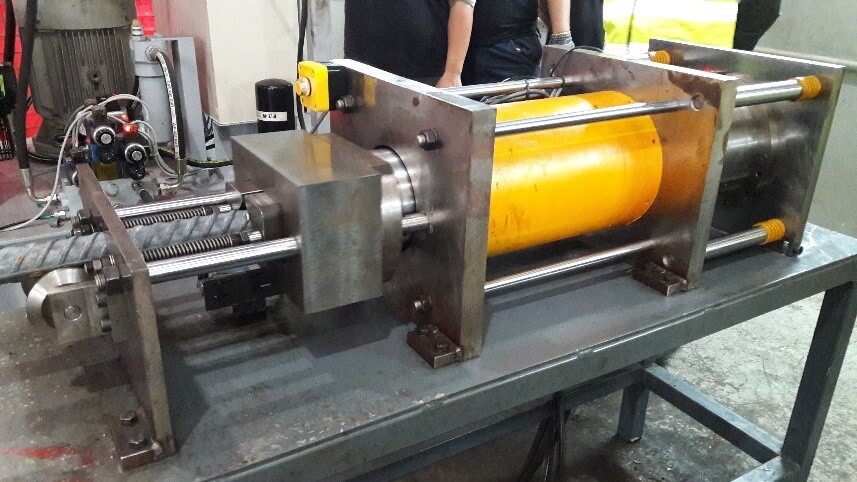
How Proof Load Improves The Reliability Of Rebar Couplers?
What Is Proof Load?
The compliance testing for couplers consist of 2 tests.
i) Tensile Strength Test- Loading to failure to determine the maximum force
ii) Slip Test/ Permanent Elongation- To capture the displacement in the thread under service loads
Before carrying out a tensile strength test, the slip test has to be carried out according to ISO 15835:2009 by stressing the coupler to 0.6fy. After the coupled bar has been loaded to 0.6fy, the load is removed and the residual displacement is measured to ensure that excessive displacement will not result in serviceability problems. This slip limit varies from standard to standard, but the limit in ISO 15835:2009 is 0.10mm.

A proof load represents a load level above the likely service stresses, but below the design yield of the rebar. When loaded to 0.75fy, it will ensure that every connection installed can achieve an acceptable safety factor against failure. A side effect of this proof loading is stress relief of the cold work done during production. This stress relief then reduces the amount of permanent elongation in the system, giving the final structure a larger safety factor against serviceability limits.
The Importance Of Proof Loaded Threading System
With proof loading, we will be able to determine beforehand and assure the threading system meets the requirements. At Leviat, proof loading facility is available upon request, every prepared bar end will undergo a proof load testing prior leaving the production factory.
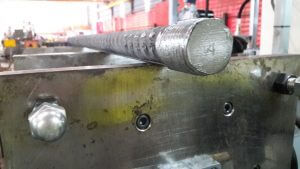
A positive indication ‘A’ will be stamped on the rebar to indicate that proof load has been carried out.
To fulfil the quality assurance of MRT Line 1 & 2 projects in Malaysia and LTA requirements in Singapore, Leviat has managed to provide proof loading for each rebar thread, to check the embrittlement of the threads and control the slip. It is our part of the quality control procedure developed to reassure good quality of threads before we supply it to each project site. After all, a good quality connection between rebars is not just settled by the quality of the coupler but also equally by the quality of the threading on rebars.
Fill In The Contact Form & Let Us Drop You A Call For A Free Consultation!
Related Articles You May Be Interested

8 Interesting Facts About Merdeka PNB 118, World’s 5th Highest Tower
Merdeka PNB 118 or also known as KL118 is a 118 floor mega tall skyscraper currently being built in Kuala Lumpur, Malaysia. Merdeka means Independence Day in Malaysian, the name of the tower commemorates the independence of Malaysia, additionally the tower will be built on the site of the former Merdeka Park. PNB is the abbreviation of Permodalan Nasional Berhad, which is Malaysia’s biggest fund management company and the owner of the tower.
Here are 8 interesting facts about Merdeka PNB 118 you would want to know:
Covers 118 Floors With An Altitude of 610-630 Meters

The tower will consist of 4 components, namely 82 stores of office floor; 18 floors are reserved for six-star luxury hotels; 18 floors for sky lobby , observation deck , as well as mechanical and electrical facilities as well as a 7-storey shopping mall of 900,000 square feet.
The Tallest Tower In Malaysia, The Third Highest In Asia, And The Fifth Highest In The World

The world’s tallest tower, Burj Khalifa in Dubai, UAE with a height of 828 meters.

The second tallest tower in the world, Shanghai Tower in Shanghai, China with a height of 632 meters.
Within a few years, the list of the world’s top 5 buildings will be:
1. Kingdom Tower in Jeddah, Saudi Arabia (1008 meters)
2. Burj Khalifa in Dubai, UAE (828 meters)
3. Wuhan Greenland Center in Wuhan, China (636 meters)
4. Shanghai Tower in Shanghai, China (632 meters)
5. Merdeka PNB118 in Kuala Lumpur, Malaysia (630 meters)
The Building Will Cost RM5 Billion And Will Be Built in 3 Phases, On A 19-Acre Land In Kuala Lumpur
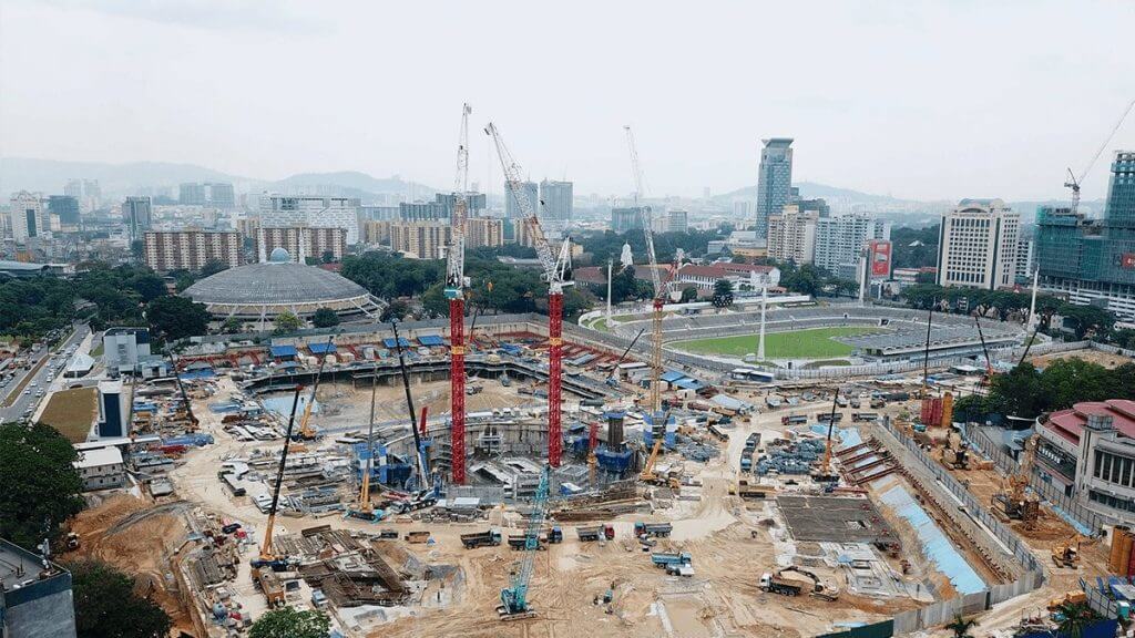
Construction for the first phase of the project has begun back in 2014.
The 3 phase project is expected to be fully completed by 2024. The first phase of the project will involve the 118 Tower and 7-storey shopping mall project, which has already begun construction back in 2014, and is scheduled to complete in 2020. PNB will ensure that the cost of construction remains on the allocated RM5 billion budget.

Aims To Grow The Economy And Provide Employment Opportunities

The project is expected to create a major economic benefit chain as high as RM11 billion. In addition to promoting economic activity, this project is expected the creation of more than 10,000 job opportunities.
Very Environmentally Friendly

The tower will be the first building in Malaysia to achieve a triple green building platinum accreditation by local and foreign bodies, including the Green Building Index (GBI)
Designed By An Australian Architecture Firm Fender Katsalidis Architects
Using custom services by architectural firms from Australia, Fender Katsalidis Architects who also built Australia’s 108 landmark in Melbourne. In addition, Fender Katsalidis Architects is also involved in the construction of luxury housing projects in Taman Duta in Kuala Lumpur.

Australia 108

Duta Park
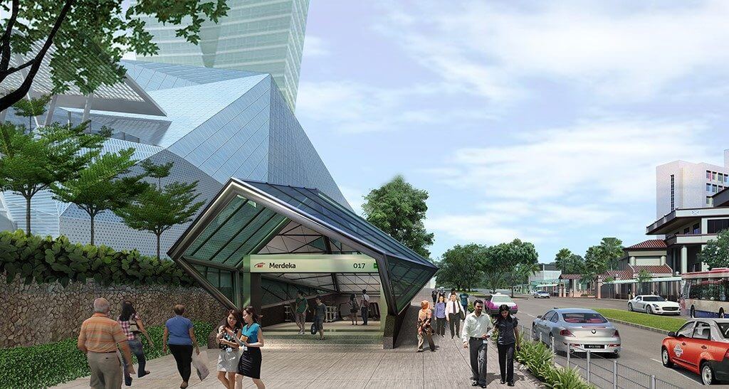
Easily Accessible
Connected to the Merdeka MRT station, the Maharajalela Monorail station – which will connect it to the rest of the LRT network.

Leviat in Malaysia Has Been Providing Technical Solutions Since The Early Stage Of The Project
Leviat has supplied more than 60,000 high quality Moment® JoinTec Couplers and Corrugated Ducts to a few contractors involved in this prestigious project.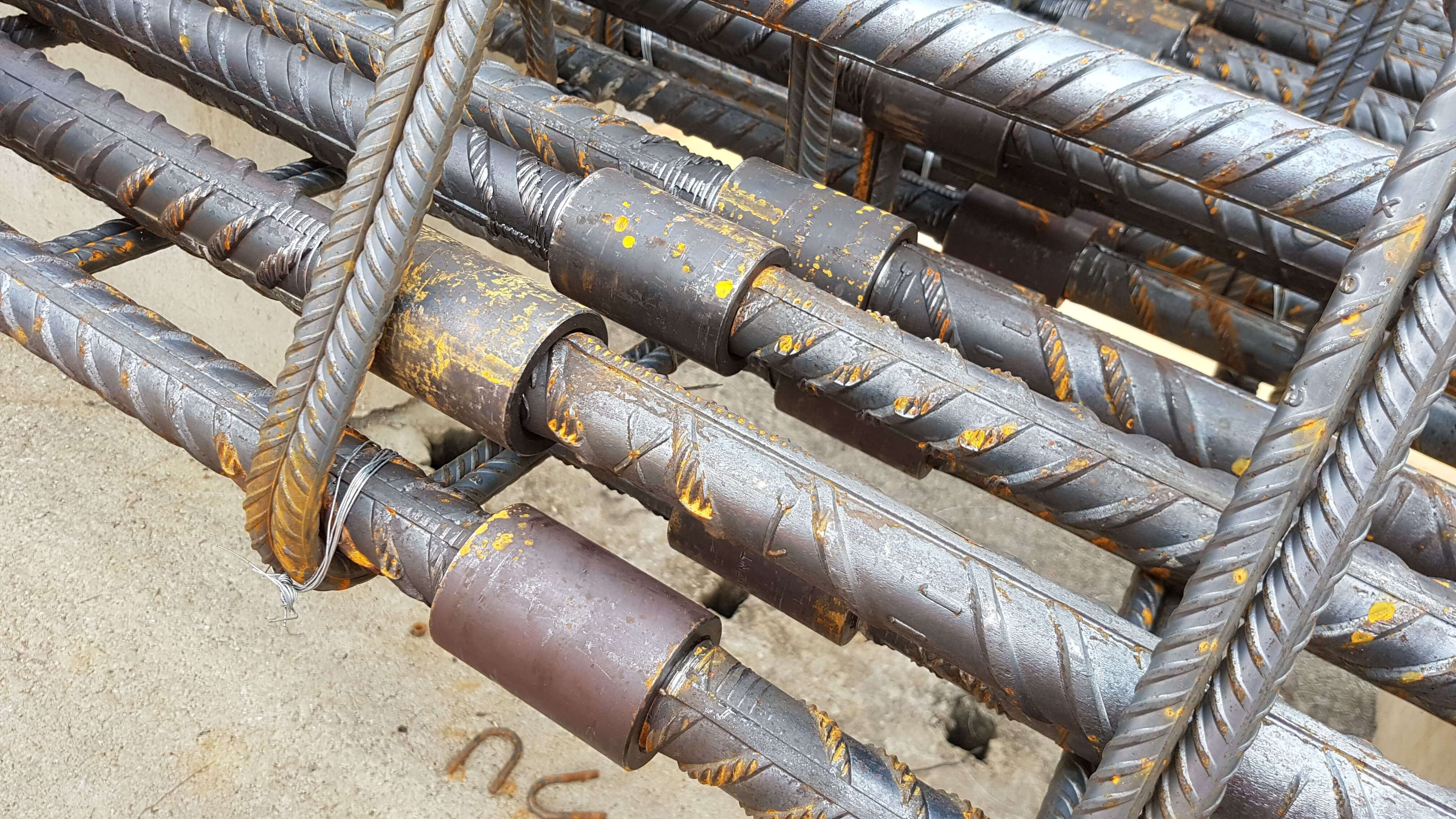

Watch the Merdeka PNB118 video produced by RSP Architects Sdn Bhd here:
Use Of Toothed Anchor Channels For Facades In Seismic Regions
Over recent years there have been some catastrophic earthquakes around the world. Therefore, it is not a surprise that Singaporean authorities are moving towards seismic design for critical structures such as Hospitals. However, it is important to highlight that designing the structures to withstand seismic actions is only part of the puzzle. In addition to the seismic actions, it is vital that the detailing of the structure, specification of the materials and selection of the products is also taken in to consideration.
In fact, some seismic tests for products are quasi static in nature and do not truly represent an actual earthquake. Therefore, additional tests such as Charpy V-Notch impact tests might also be needed to prove fitness for use in a seismic region.
In the case of a façade anchoring, where a failure can easily see a 200+kg panel falling from the side of a high rise structure, this suitability is especially critical as the current method of anchoring them to the structure usually uses cast in channels that only have high load carrying capacity in 2 axes.
With large lateral ground accelerations during an earthquake, the applied loads in the third axis (along the length of the channel) are much higher when seismic actions are considered. This has led to the development of serrated or toothed channels which have a significantly higher capacity in the third axis.
Anchor Channels are regulated in Europe under the European Assessment Document (EAD) 330008-02-06014 and designed with the standard PrEN 1992-4. In the United States of America they are tested to AC232 – Acceptance Criteria for anchor channels in Concrete5 by the Evaluation Service of the International Code Council (ICC-ES), but currently in Singapore we do not have a certification process and tend to follow the European Technical Assessments (ETAs). These documents all use the same design principles for tension and shear loads perpendicular to the longitudinal axes of the anchor channel. Since February 2016, AC232 also covers loads in the longitudinal axis of the anchor channel and includes the design for seismic conditions allowing their use in all seismic design categories (A – F) provided the channels are capable of providing resistance in all three axes. A common approach to achieve a load capacity in the longitudinal direction is to use the above mentioned serrated channels.
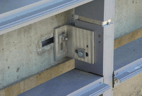
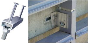
Serrated channels contain teeth along the inside of the channel lips and are used with channel bolts with a matching serration. The channel and bolt serrations create an interlock between the two surfaces which provides a positive connection capable of resisting shear loads in the longitudinal direction of the channel axis. Toothed Anchor Channels have been used in multiple projects worldwide including the anchoring of the curtain wall façade of the Broad Museum in Los Angeles or the Tanjong Pagar Mixed Development project which required particular attention to seismic design.
Plain anchor channels with plain T-bolts can take over longitudinal loads based on the friction between the channel and the T-bolt, but the capacity relies on the torque of the T-bolt. International standards and regulations do not allow friction based connections and thus plain anchor channels in combination with plain T-bolts cannot be used in applications that require longitudinal loading.
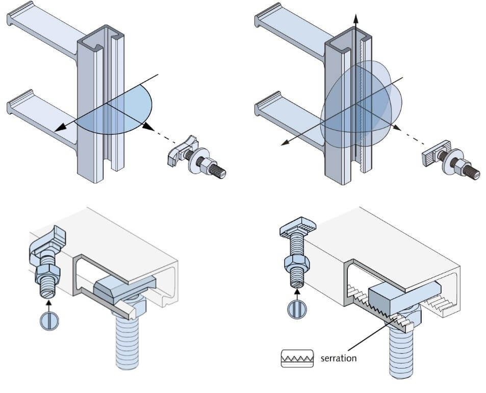
Anchor channels with plain and toothed lips and T-bolts
The design approach as described in AC 232 allows for a design of serrated anchor channels to provide a safe and reliable way to connect façade panels to concrete. The use of the slotted holes will still allow the adjustability required to overcome building tolerances and the absence of welding will increase safety and productivity.
Related Articles You May Be Interested

Concept Designs for Kuala Lumpur-Singapore High Speed Rail Stations Unveiled
MyHSR Corp has presented the architectural concept designs for all seven stations of Kuala Lumpur-Singapore HSR in Malaysia including Bandar Malaysia, Bangi-Putrajaya, Seremban, Melaka, Muar, Batu Pahat and Iskandar Puteri. The designs of each station were conceptualised to reflect not only the diverse heritage, culture and identity of each city along the HSR corridor, but also demonstrates the growth vision that will be accomplished with the KL-SG HSR.
Bandar Malaysia- My Gateway
Bangi-Putrajaya- My People

Seremban- MyVision

Melaka- MyHeritage

Muar- MyFuture

Batu Pahat-My Culture

Iskandar Puteri-My Encounter

Source: HSR Corp
Related Articles You May Be Interested

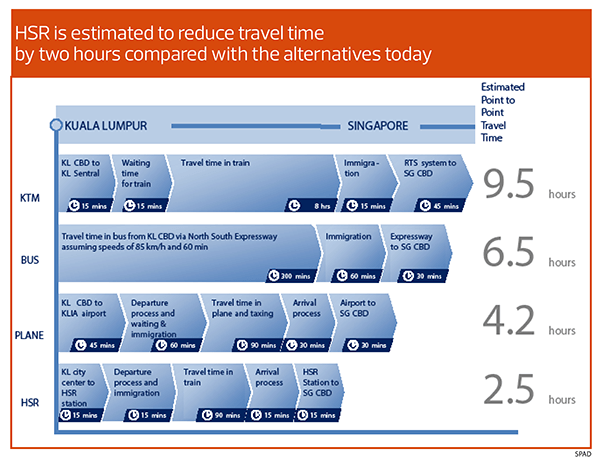
10 Things To Know About The Kuala Lumpur-Singapore High Speed Rail

First conceived in 2013, the Singapore-Kuala Lumpur High Speed Rail (HSR) has been four years in the making. Malaysian Prime Minister Najib Razak signed an agreement with Singapore Prime Minister Lee Hsien Loong in Putrajaya on July 19 2016. The rail project has been billed as a “game-changer” that will boost connectivity, strengthen economic ties and forge closer ties between people of both countries.
Here are 10 points to note about the HSR project:
Estimated Operational Date
8 Stations
The planned stations are Kuala Lumpur, Putrajaya, Seremban, Ayer Keroh, Muar, Batu Pahat, Iskandar Puteri and Jurong East. The Singapore station will be located at Jurong East, where Jurong Country Club is currently located.
350km Total Distance
Shorter Travel Time
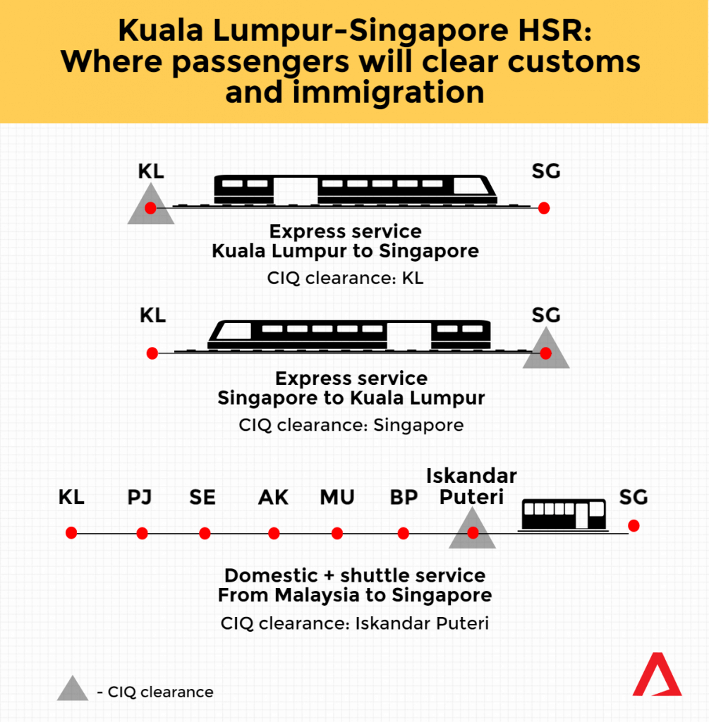
3 Services With 2 Separate Operators
The Domestic service will consist of stations within Malaysia only, from Kuala Lumpur to Iskandar Puteri stations. Having 2 different OpCos will allow the HSR to better cater to the different needs of their passenger profiles. OpCo Domestic will also give Malaysia more flexibility to regulate its own internal service. The Express and Shuttle service will be given scheduling and operational priority over the Domestic Service.
Each Country Is In Charge Of Its Own Stations And Infrastructure
This will be undertaken by MyHSR Corporation in Malaysia and the Land Transport Authority (LTA) in Singapore.
Implementation Of A Bilateral Committee
A working-level joint project team will also handle all matters that require coordination and joint engagement between Singapore and Malaysia.
Co-located CIQ Concept (Seamless Travel)
International-bound passengers will need to go through CIQ clearance by both Singapore and Malaysia authorities only at the point of departure, ensuring swift and seamless travel.
Biggest Challenge: Line's Alignment In Malaysia
What they believe is tougher is the drafting of the tender documents and contracts before 2021, as well as the biggest challenge of finalizing the line’s alignment of the 350-kilometre long route, much of which is in Malaysia.
Round Trip Under RM400
In Singapore, prices are expected to hover around S$80-90 for a trip, though it is unclear as to whether or not said fare includes a return journey.
Related Articles You May Be Interested